
To determine the actual length of a path through a number of cells the Incremental Length operation is used. Incremental Length works similar to Incremental Linkage to the extent that Incremental Linkage is used implicitly to determine the linkage, from which the length is inferred. Incremental Length then applies the factor by which the cell resolution has to be multiplied to yield the length of the linear features in any cell.
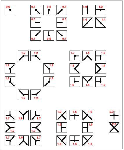

Incremental Length cell values indicate factor for calculating length of linear features. © Thinkspace
It should be noted that Incremental Length calculates the factor for inferring the total length of all linear features in any cell. When uncritically applied to deriving the time of traversing a cell, this function may not yield exact results, since the time of passing straight through a cell may differ from the calculated value, which takes into account all linear features in that cell, even those that are not traversed. The smaller the cell resolution and the higher the average speed, the more negligible this error becomes.
Assessing discrepancy between actual path length
and length inferred from Incremental Linkage
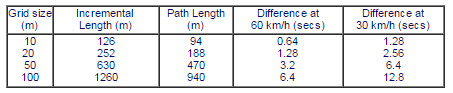
The figure and table above demonstrates an example of this “error”. The bold line is the path sought; the shaded cells indicate where the Incremental Length factor deviates from the actual length. The table shows how cell resolution and average speed influence the magnitude of the error.
To determine the length of a particular road stretch, this stretch first has to be separated, then made subject to the Incremental Length operator to find the correct length. Whether this last procedure is absolutely necessary will depend on the cell resolution and whether deriving the actual path length is strictly required as a result of the task in question.
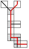
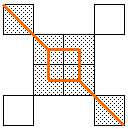
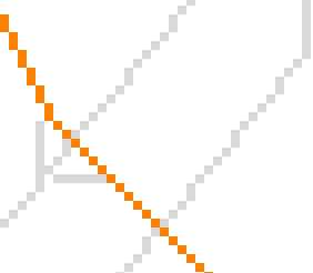
A special case, illustrating the discrepancy between inferred and actual path length, as described previously, appears at crossroads and junctions and deserves particular attention, especially at non-90-degrees junctions, as shown in the following example:
Sought path through a junction
The actual path sought is a straight line through the junction, indicated by the shaded cells. The bold lines indicate the actual linear features. Here, the actual path length is cell resolution x 5.6 (1.4 x 4).
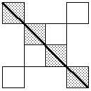
Inferred path, as result of Incremental Length/ Incremental Linkage
In order to justify the inferable directions, the Incremental Length operator will link to many cells together, as shown by the shaded cells and bold line. The inferred path is equal to cell resolution x 8.2 (1.7 x 2 + 1.4 x 2 + 1 x 2), thus overestimating the actual path over this section by 2.6 x cell resolution. Unless there is substantial difference in cost-of-passage between the two roads that cross each other, which then prohibits the off-path cells from being included in the added proximity surfaces, this error will occur in most cases with such junctions.
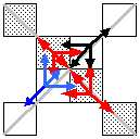
Correctly modelled junction, linkage indicated by bold lines, direction indicated by arrows
A solution to avoid this from the beginning, before finding the least-cost path, would be to model the linkage correctly, and allow the direction to flow differently. The fact that it is possible to completely detach the direction of the flow in a network from the underlying linear feature is indeed an interesting observation concerning the modeling of networks in raster GIS.
The above can also be demonstrated by an example from the study area. Note the linked square in the left image, as opposed to the straight line in the right image:
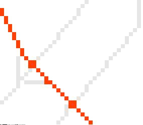
(a) Least-cost path using generically inferred directions
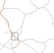
(b) Location of a and c in study area
(c) Least-cost path using manually inferred directions
