
The second step to creating a road network in raster GIS is to impose constraints on the flow that can take place from cell to cell. The value assigned to the centre cell in a 3×3 window indicates the directions the flow can take in and or out of this cell. Figure 1-5 shows how a cell value of 10 is inferred from flow in direction 8 and 2.
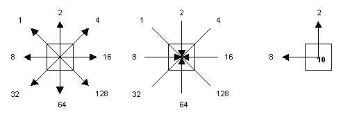
Tomlin’s directional identifiers: Cell values indicate possible flow direction in or out of cell

The directional identifiers that are to be assigned to any given cell in a road network can be directly inferred from the Incremental Linkage values, i.e. Incremental Linkage value 28 yields directional constraints value 10, and so on. The transition from Incremental Linkage to Directions is done through a straightforward reassigning of the cell values in the Incremental Linkage map layer to corresponding values in the Directions map layer. More specific constraints, like one-way directions or dead-end roads, which are not directly inferable from the mentioned linkage values, will have to be assigned manually.
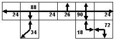
Inferring flow directions from Incremental Linkage values in figure above

