Tag Archives: flow direction

MFworks Tutorial – 03 Incremental Linkage

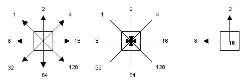
This operation infers the lineal characteristic of raster cells, by equating consecutive locations with a set of straight lines between them (Figure 1-3). Based on its relations with neighboring cells that have the same attribute value, each cell is given a linkage value indicating how it is linked to other cells.

Incremental Linkage, cell value infers the linear structure it represents.
© Thinkspace

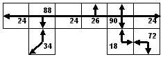
By assigning a value to each cell equivalent to the linear feature it represents it is possible to create a network similar to a road network. The smaller the cell resolution, the better the real-world road network will be approximated by this procedure.

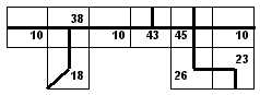
Building a road network using Incremental Linkage from
figure 1-3 with cell values representing linear features

The second step to creating a road network in raster GIS is to impose constraints on the flow that can take place from cell to cell.

MFworks – step by step

MFworks Tutorial – 04 Directional Identifier

The second step to creating a road network in raster GIS is to impose constraints on the flow that can take place from cell to cell. The value assigned to the centre cell in a 3×3 window indicates the directions the flow can take in and or out of this cell. Figure 1-5 shows how a cell value of 10 is inferred from flow in direction 8 and 2.


Tomlin’s directional identifiers: Cell values indicate possible flow direction in or out of cell

The directional identifiers that are to be assigned to any given cell in a road network can be directly inferred from the Incremental Linkage values, i.e. Incremental Linkage value 28 yields directional constraints value 10, and so on. The transition from Incremental Linkage to Directions is done through a straightforward reassigning of the cell values in the Incremental Linkage map layer to corresponding values in the Directions map layer. More specific constraints, like one-way directions or dead-end roads, which are not directly inferable from the mentioned linkage values, will have to be assigned manually.


Inferring flow directions from Incremental Linkage values in figure above

MFworks – step by step

MFworks Tutorial – 05 Cost surface

Usually, to generate a cost-of passage surface, several variables will be collapsed into one layer. These variables might be road class, average speed, traffic density, and congestion during specific time of day or other factors that contribute to the overall cost variable. The cost-of-passage surface can be defined by a variety of measurement units: time, fuel consumption, money or other possible cost units, for which the least cost passage is to be determined.

Using average speed and time as a means of inferring cost-of-passage is among the most common approach in network analysis, since it is easy to use and calculate. However, “least cost” does not always need to be “least time”; it may just as well be least fuel, least length, or any least cost variable that can be implemented in a cost-of-passage surface.

Cost surface, with values indicating impedance to travel (cost) across the cells.

MFworks – step by step